Choosing the correct number of solar array brackets affects safety, panel alignment, and long-term system performance. A roof may look simple from the ground, yet its dimensions, slope, material, and exposure can change the calculation. This guide explains five practical ways to estimate bracket requirements before installation begins. It focuses on measurable details, such as panel length, rail spans, attachment points, wind conditions, and manufacturer spacing limits.
Many installers begin with a layout drawing and confirm the result through structural guidance. So, how to calculate the number of brackets for a solar array? The answer usually requires more than dividing roof length by panel width. You must identify every panel row, calculate rail lengths, and determine how many supports each rail needs. Edge zones often need closer spacing. Snow and strong wind can also increase the required attachment points. Always compare your estimate with the racking manufacturer’s instructions and, when necessary, a qualified structural professional. Small mistakes matter. A missing bracket can create movement, while excessive brackets may damage roofing materials or increase project costs. These five methods are useful, but none is perfect alone. Site measurements can be incomplete, and older roofs may hide weaknesses. Careful verification remains essential.
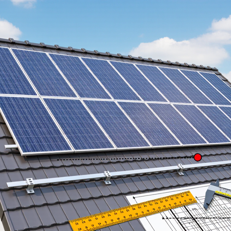
5 Best Ways to Calculate Solar Array Brackets Needed?
Solar bracket quantity begins with the panel layout, not the roof area alone. Draw the array in rows and columns, showing module length, width, orientation, and service gaps. Count one support position at each approved clamp zone. A neat drawing can still be wrong.
Use five practical checks: count modules, calculate rail spans, mark mid-clamps, add end-clamps, and locate roof attachments. Rail spacing must follow the panel’s installation manual and the mounting system’s tested limits. A 20-panel layout may need 40 end clamps, plus 38 mid-clamps, if panels form one continuous row. Split rows change that number. Small gaps matter.
Roof conditions decide whether the layout is acceptable. Check rafter spacing, roof edges, wind exposure, snow load, and waterproofing details. ASCE 7-22 provides the structural load framework used for wind and snow design in many projects. The IEA PVPS Trends 2024 report recorded about 456 GW of new solar capacity in 2023, showing how quickly installation practices are scaling. Yet volume does not replace site verification. Compare drawings with actual rafters. Confirm every bracket position before drilling. Installers sometimes overcount brackets while undercounting rail splices and grounding parts. That mistake deserves a second review.
| Method | What to Identify | Calculation Method | Illustrative Project Data | Estimated Brackets or Mounting Parts | Important Mounting Requirement |
|---|---|---|---|---|---|
| 1 | Calculate by panel quantity Use the number of modules and the end or middle position of each module. |
For a continuous row: End clamps = 2 per row Mid clamps = 2 × (panels per row − 1) |
20 panels arranged as 2 rows of 10 panels. Each row has 2 end clamps and 18 mid clamps. |
4 end clamps + 36 mid clamps = 40 module clamps. Add approximately 5% spare parts: 42 clamps. |
Confirm that the clamp profile matches the panel frame height and that the clamps are placed within the module manufacturer’s permitted zones. |
| 2 | Calculate by rail length Determine how many mounting rails are required beneath each panel row. |
Total rail length = row length × rails per row × number of rows Rail pieces = total rail length ÷ stock rail length |
Panel width: 1.13 m 10 panels per row Row length: 10 × 1.13 = 11.30 m Two rails per row and 2 rows. |
Total rail length: 11.30 × 2 × 2 = 45.20 m. With 3.60 m rail sections: 45.20 ÷ 3.60 = 12.56, so use 13 rail sections, subject to splice and overhang limits. |
Allow for thermal expansion, approved rail splices, maximum unsupported spans, and the required rail overhang at both ends. |
| 3 | Calculate by roof attachment points Count the roof brackets, hooks, or fasteners needed to transfer loads to the structure. |
Attachment points = number of rail lines × supports per rail line The support spacing must be based on the roof structure, rail capacity, and project design loads. |
4 rail lines supporting the array. 6 roof attachments per rail line. Total roof attachment locations are calculated before adding spares. |
4 × 6 = 24 roof attachments. Add 10% installation allowance: 24 × 1.10 = 26.4, so prepare 27 attachment assemblies. |
Attachments must connect to adequate rafters, trusses, or structural members. Flashing and waterproofing details are required for penetrations. |
| 4 | Calculate by layout zones and obstructions Separate the array around ridges, vents, skylights, valleys, setbacks, and access paths. |
Calculate each uninterrupted zone separately: Zone brackets = end clamps + mid clamps + rail supports Then add any extra rails, splices, or edge components caused by the split layout. |
Zone A: 12 panels in one row. Zone B: 8 panels in one row. The zones are separated by a roof vent and a required access gap. |
Module clamps: 2 rows × 2 end clamps + 2 × [(12 − 1) + (8 − 1)] mid clamps = 48 clamps. Additional rail splice and support hardware may be required at the zone boundaries. |
Maintain required roof edges, fire-access pathways, drainage clearances, and service access. Do not place brackets over unsuitable roof areas or obstructions. |
| 5 | Verify by wind, snow, and structural loads Use the governing site loads to confirm whether the preliminary bracket count is adequate. |
Check rail span, attachment spacing, uplift, downward pressure, sliding, fastener capacity, and roof-member capacity. Use the most demanding load case rather than relying only on a simple panel-count estimate. |
Preliminary design: 20 panels, 4 rail lines, and 24 roof attachments. A high-wind or heavy-snow location may require closer support spacing and additional attachments. |
The final quantity is the greater of the layout estimate or the quantity required by structural calculations. Example: if the design requires 8 attachments per rail line, use 4 × 8 = 32 attachments, not 24. |
Confirm local building-code requirements, roof condition, fastener pull-out resistance, rail deflection limits, and the structural capacity of the supporting members. |
| Planning note: These figures are illustrative planning values, not a construction specification. Final bracket, rail, clamp, fastener, and attachment quantities should be verified against the actual panel dimensions, roof geometry, mounting system instructions, local code requirements, and site-specific structural calculations. | |||||
Start with the panel layout, not the roof area. Draw rows, columns, panel orientation, dimensions, and service gaps. A neat drawing can still mislead.
Count each approved clamp position along the rail. For 20 panels in one continuous row, you might need 40 end-clamps and 38 mid-clamps. Split rows change the count.
Rails may need mid-rail connections, splices, or shared attachments. These parts can change the final quantity. The simple rule is only a starting estimate.
Check rafter spacing, roof edges, wind exposure, snow loads, and waterproofing. Edge and corner areas may require closer attachments. Do not trust the drawing alone.
Mark every bracket, rail line, panel gap, rail overhang, and roof attachment. Show rafters, seams, or purlins when visible. Small gaps matter.
Check the current installation manual and engineering tables. Confirm bracket type, maximum rail span, torque value, and allowable load. Similar-looking parts may not be approved substitutes.
They should be reviewed separately from brackets. Installers sometimes count brackets correctly but miss splices or grounding parts. That mistake deserves another review.
A small allowance can help with damaged or missing parts. Too many extras increase cost and storage needs. Measure twice.
More installations encourage consistent methods, but volume does not replace site verification. Compare the layout with actual roof members before drilling. Field conditions can disagree.
Determining the right number of solar array brackets begins with identifying the panel layout and the mounting method, whether the system is installed on a roof or on the ground. Measure the available area carefully, allowing for access paths, roof edges, panel orientation, and spacing between modules. Next, use the panel dimensions, rail design, and permitted load limits to establish suitable bracket spacing and estimate the basic quantity required for each panel row.
How to calculate the number of brackets for a solar array? Start by dividing each mounting rail or panel section according to the recommended spacing, then add brackets at key connection points and row ends. The preliminary count should be adjusted for local wind exposure, snow loads, roof condition, ground stability, and the strength of the supporting structure. Finally, compare the result with the installation instructions and load tables supplied for the chosen mounting system. A qualified installer should verify the final layout before construction.

 Soltrux Solar