Solar panels often receive attention, while their mounting systems remain overlooked. Yet rails, clamps, bolts, and roof attachments carry constant mechanical stress. How to maintain solar panel mounting systems? The answer begins with regular, methodical inspections rather than occasional repairs. A loose clamp can allow movement, vibration, or water entry. Small oversights matter. Routine care protects the array, the roof, and long-term energy performance.
A practical maintenance plan starts with a visual inspection every few months. Look for corrosion, cracked brackets, displaced rails, loose fasteners, and damaged cable clips. Check areas near roof edges, where wind exposure can be stronger. Remove leaves, nests, and accumulated debris without dragging tools across the panels. After storms, inspect the system again. Weather can reveal weaknesses that were invisible during calm conditions. Photographs and dated notes help compare changes over time. They also help technicians identify recurring problems.
Maintenance should follow the manufacturer’s instructions and the site’s structural requirements. Fasteners need appropriate tools and torque settings, not guesswork. Roof penetrations deserve careful attention because failed seals may cause hidden moisture damage. Electrical work should be handled by qualified professionals, especially when connectors or grounding components appear damaged. Do not walk on modules or climb unstable structures. Safety must remain practical, not merely written in a checklist. Even experienced owners can miss a small defect. That is why periodic professional inspections remain valuable. This guide explains reliable maintenance habits, while recognizing that every roof, climate, and mounting design requires thoughtful judgment.
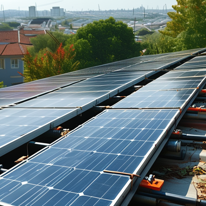
How to Maintain Solar Panel Mounting Systems?
Establish a 6–12-Month Inspection Cycle for Solar Mounting Hardware
A planned inspection cycle protects the structure beneath every solar panel. Check mounting hardware every six to twelve months, then shorten the interval in coastal, snowy, or dusty locations. Salt air can accelerate corrosion around bolts, rails, and clamps. Heavy snow may also shift load patterns. Small movement matters.
During each visit, inspect exposed metal for rust, cracks, bending, and loose connections. Look beneath the panels for displaced rails, damaged fasteners, and cable contact points. Use a calibrated torque wrench when checking critical fasteners. Do not guess. Follow the installation specifications and local safety requirements. A visual check alone may miss insufficient clamping force.
Record the inspection date, weather conditions, visible defects, torque readings, and corrective work. Photographs of the same connection can reveal gradual movement over time. Keep records. However, a checklist is not infallible. Dirt can hide early corrosion, while restricted access may leave some areas unexamined. Qualified personnel should assess structural damage or uncertain findings. In practice, technicians sometimes focus heavily on bolts and overlook roof penetrations, drainage paths, or sealant deterioration. That oversight is easy to repeat. Review the inspection process annually and adjust it when the site, climate, or system condition changes.
| System Area | Inspection Item | Inspection Method and Scope | Typical Acceptance Criteria | Recommended Cycle | Action if Defect Is Found |
|---|---|---|---|---|---|
| Module-to-Rail Connections | Module clamps and fasteners | Visually inspect end clamps, mid clamps, bolts, washers, and threaded connections. Check for movement, missing hardware, corrosion, or clamp displacement. | Clamps remain fully seated on the module frame; no missing parts, visible deformation, severe corrosion, or looseness. | Every 6–12 months | Isolate the affected area if necessary. Replace damaged parts and tighten or retorque fasteners according to the approved installation specification. |
| Rail System | Rail alignment and deflection | Check rail straightness, splice locations, unsupported spans, and visible sagging. Compare the array with the original layout and inspect after severe weather. | Rails remain aligned and firmly supported, with no abnormal bending, twisting, cracking, or movement. | Every 6–12 months | Restrict access to the affected section and have a qualified person assess structural loading. Replace or reinforce damaged rails where required. |
| Rail Splices | Splice connectors and expansion gaps | Inspect splice plates, splice bolts, rail interfaces, and movement gaps. Look for shifted rails, loose connections, or contact between rails where movement is expected. | Splices are secure, rails are properly aligned, and movement gaps follow the mounting system’s approved design. | Every 12 months | Reposition or replace splice components and correct rail alignment using the approved installation details. |
| Roof Attachments | Flashing, roof penetrations, and attachment points | Inspect flashing, sealant, attachment bases, standoffs, and surrounding roofing for cracks, gaps, water staining, uplift, or movement. | No visible water intrusion, open gaps, lifted flashing, cracked sealant, or movement at attachment points. | Every 6–12 months | Arrange prompt repair by a qualified roofing or solar professional. Do not cover active leaks without correcting the underlying defect. |
| Ground-Mounted Foundations | Posts, foundations, and soil conditions | Check exposed posts, concrete or driven foundations, visible settlement, erosion, frost heave, standing water, and signs of soil movement. | Foundations remain stable and plumb, with no significant settlement, cracking, undermining, exposed damage, or abnormal frame movement. | Every 6–12 months | Barricade unstable areas and obtain a structural assessment. Repair drainage, soil erosion, foundations, or posts as appropriate. |
| Structural Members | Beams, brackets, braces, and members | Visually inspect steel or aluminum members for cracks, bending, galvanic corrosion, coating failure, or contact with dissimilar materials. | Members are straight, securely connected, and free from cracks or corrosion that reduces cross-section or connection strength. | Every 12 months | Document the location and severity. Replace structurally compromised components; do not weld or modify load-bearing parts without engineering approval. |
| Fastener Condition | Corrosion and material compatibility | Examine bolts, nuts, washers, threaded inserts, and contact areas for rust, white corrosion products, staining, or incompatible-metal contact. | Fasteners retain their intended strength and show no advanced corrosion, stripped threads, or loss of bearing surface. | Every 6–12 months | Replace affected fasteners with compatible components. Correct moisture traps and isolate dissimilar metals where required by the design. |
| Wind and Weather Exposure | Signs of uplift, vibration, or storm damage | Perform an additional visual inspection after high winds, hail, heavy snow, flooding, earthquakes, or other unusual events. | No shifted modules, displaced clamps, bent rails, loosened attachments, impact damage, or abnormal vibration marks. | After severe weather | Keep personnel away from unsafe areas. Stop work if electrical or structural hazards are present and arrange qualified inspection and repairs. |
| Snow and Debris Load | Accumulation and drainage paths | Check whether snow, leaves, dirt, or other debris is accumulating against lower module edges, rails, drains, or roof surfaces. | No accumulation creates abnormal loading, blocks drainage, causes corrosion, or contacts electrical equipment. | Seasonally and after storms | Remove accumulation only with safe, non-damaging methods. Follow site safety procedures and avoid applying loads directly to modules. |
| Bonding and Grounding Hardware | Grounding clips, bonding jumpers, and lugs | Check that bonding devices are present, secure, accessible where required, and free from corrosion or paint contamination at contact points. | Grounding paths are continuous and connections are secure, clean, and installed in accordance with the approved electrical design and local requirements. | Every 12 months | Have a qualified electrical professional test and repair the grounding or bonding system before returning the affected equipment to service. |
| Cable Management | Cable clips, ties, and routing near mounting hardware | Inspect cable supports for breakage, UV damage, abrasion, sharp edges, excessive sag, and contact with the roof or metal structure. | Cables are supported, protected from abrasion, clear of sharp edges and standing water, and not under excessive tension. | Every 6–12 months | Replace damaged supports and reroute cables using suitable UV-resistant hardware. Electrical repairs should be completed by qualified personnel. |
| Documentation and Records | Inspection log and corrective-action tracking | Record inspection date, weather conditions, inspected areas, photographs, defects, measured values, responsible person, and completion status. | Records are complete, traceable, and allow comparison with previous inspections and the original system documentation. | At every inspection | Assign a due date and responsible person for each defect. Keep completed work records and updated photographs with the site maintenance file. |
Inspection priority: Use a 6-month cycle for systems in coastal, corrosive, high-wind, heavy-snow, or high-humidity environments. A 12-month cycle may be suitable for stable, low-risk sites when permitted by local requirements and the system documentation. Any safety-critical, structural, electrical, or water-intrusion defect should be assessed without delay by a qualified professional.
Inspect accessible fasteners at least twice yearly. Recheck them after severe storms and the first seasonal temperature cycle.
Use a calibrated torque wrench. Follow the specified value for dry or lubricated threads. Do not guess.
Use removable inspection paint on checked bolts. Record the date, location, torque reading, and tool used.
No. Over-tightening can damage threads or weaken the connection. The specified value is safer than extra force.
Review wind uplift, sideways wind, snow, and seismic forces. Roof height, panel tilt, edge zones, and local exposure can increase loads.
Look for red rust, white oxidation, dark streaks, loose fasteners, elongated holes, and displaced rails. Small movement matters.
Check penetrations for cracks, lifted edges, brittle surfaces, and gaps. Remove leaves, mud, nesting material, and hardened debris from drainage paths.
No. Torque checks confirm only one connection detail. A qualified structural review may still be needed. That matters.
Pause before making assumptions. Verify the original installation specifications, then document the new findings with photographs.
Request assessment when corrosion reaches structural connections, seals fail repeatedly, rails bend, panels shift, or water pools beneath the array. I may miss something.
How to maintain solar panel mounting systems? Start by establishing a regular inspection cycle every 6–12 months, with additional checks before severe weather or seasonal load events. Inspect rails, clamps, brackets, bolts, seals, drainage paths, and support connections for movement, wear, corrosion, water accumulation, or other signs of deterioration. Fastener torque should be verified against the mounting manufacturer’s specifications and the design loads used for the installation, including applicable wind, snow, and seismic conditions under ASCE 7.
A well-maintained system should also have reliable grounding and bonding, inspected in accordance with the project’s applicable electrical requirements, including IEC 62548 and UL 2703. Keep clear maintenance records with inspection dates, measured torque values, photographs, identified defects, and completed repairs. Damaged, loose, or corroded components should be replaced promptly with compatible parts before seasonal stresses increase, helping preserve structural stability, electrical safety, drainage performance, and the expected 25–30-year service life of the solar mounting system.

 Soltrux Solar